This page will describe how to install CoCoVGA in a Color Computer 2 with a Korean-manufactured mainboard which contains a 6847T1 (marked XC80652P). Drilling the case to mount the button board is not necessary, but recommended.
For installation of one of Zippster's (Ed Snider's) combination composite + audio boards, see his page.
Required Tools
For CoCoVGA main board
- Phillips screwdriver to open the CoCo 2 case
- Small flat screwdriver and/or DIP chip puller to remove 6847T1 (if socketed)
- Small wire cutters, needle-nose pliers, soldering pen and solder wick or solder sucker to remove 6847T1 (if not socketed)
For CoCoVGA button board
- A template, either:
- Printer and ruler to print template and check that it is full size and tape to temporarily attach to CoCo case -OR-
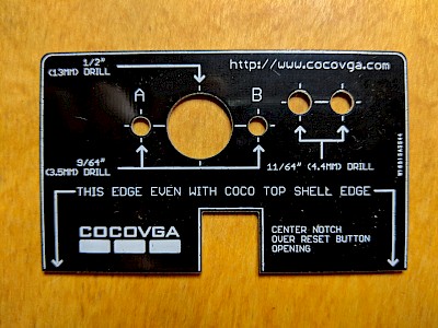
- a PCB template, which may have been included in your kit
- Drill and bits with diameters 3.5mm (~9/64 in), 4.4mm (~11/64 in), and in various steps up to 13mm (~1/2 in) and/or a round file, knife or razor blade
- Small flat or Phillips screwdriver and pliers to attach button board to case using machine screws, standoffs, and nuts
For CoCoVGA audio connection
- Drill and bit with diameter 6mm (~1/4 in)
- A soldering iron and solder
- Wire strippers, a knife, or razor blade to aid in removal of wire insulation
Parts in Kit
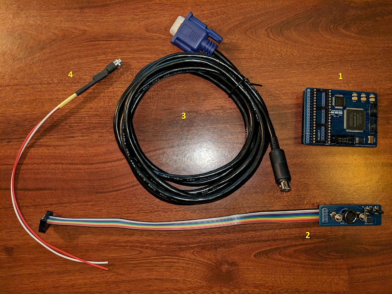
A CoCoVGA kit contains the following items:
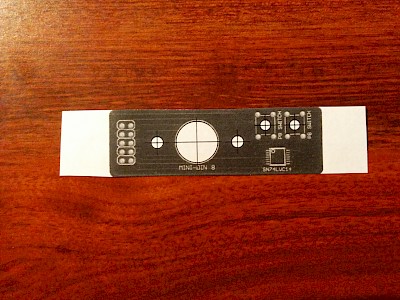
- CoCoVGA main board model T1 (KMC1 is pictured here but they are very similar in appearance)
- CoCoVGA button board
- DIN-to-HD15 (VGA) cable
- Audio jack with red and white wires, if appropriate for your installation
- 2 machine screws with hex standoffs and nuts (shown attached to button board)
- PCB drill template for button board (not shown), if available for your installation
Installation
Step 1 - Open the case
Disconnect the CoCo 2 from power and all peripherals.
Use a Phillips screwdriver to remove the 6 screws from the underside of the Color Computer 2 and set the screws aside for later.
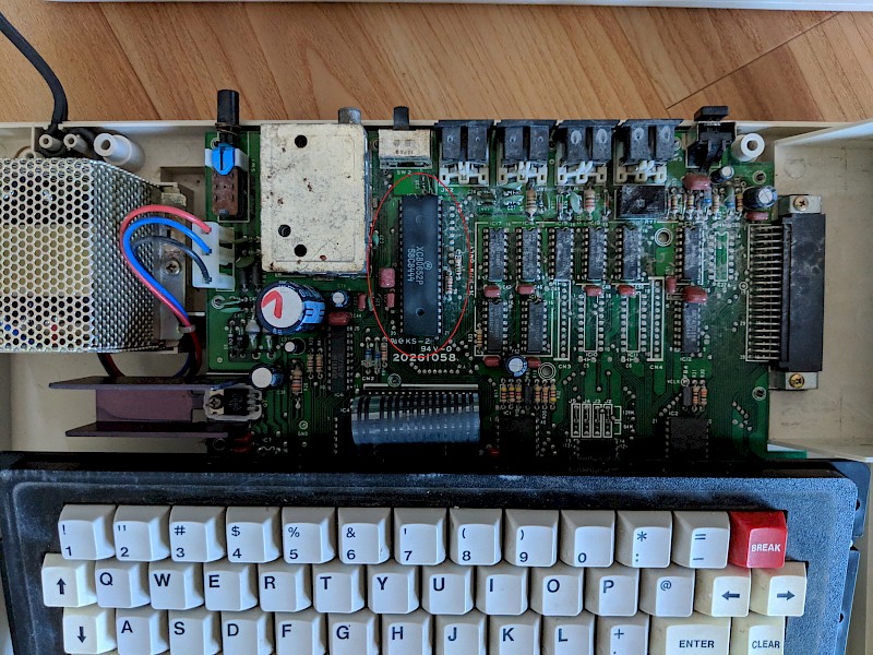
Set the CoCo 2 back down on its base and remove the case top.
Step 2 - Remove/relocate 6847T1
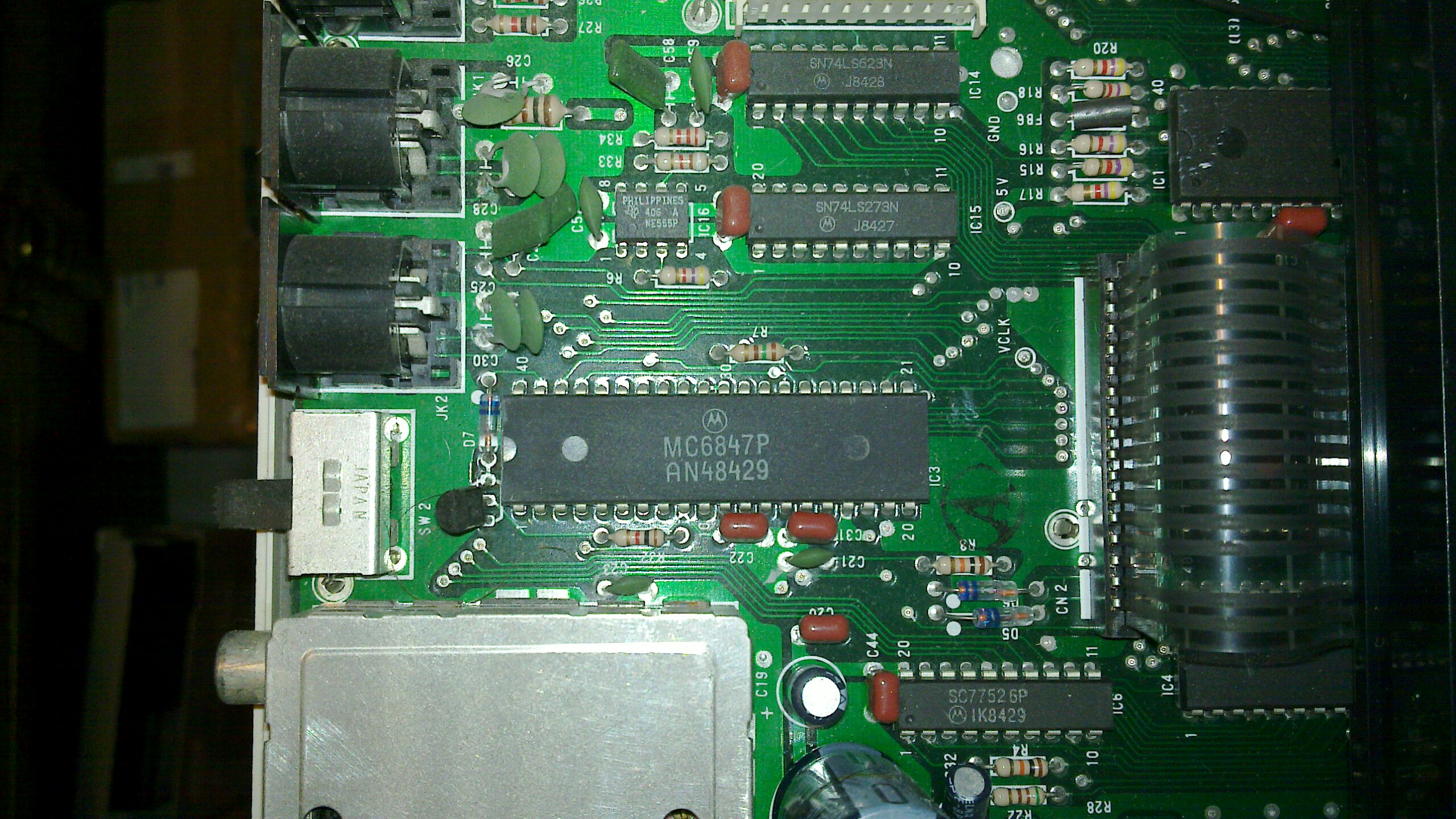
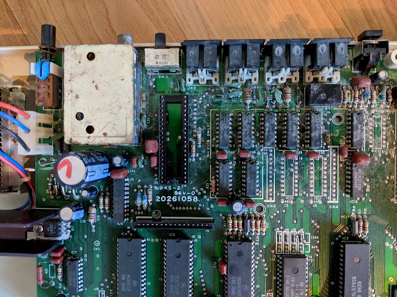
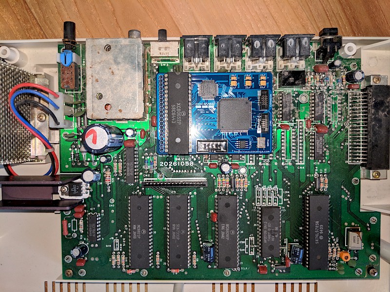
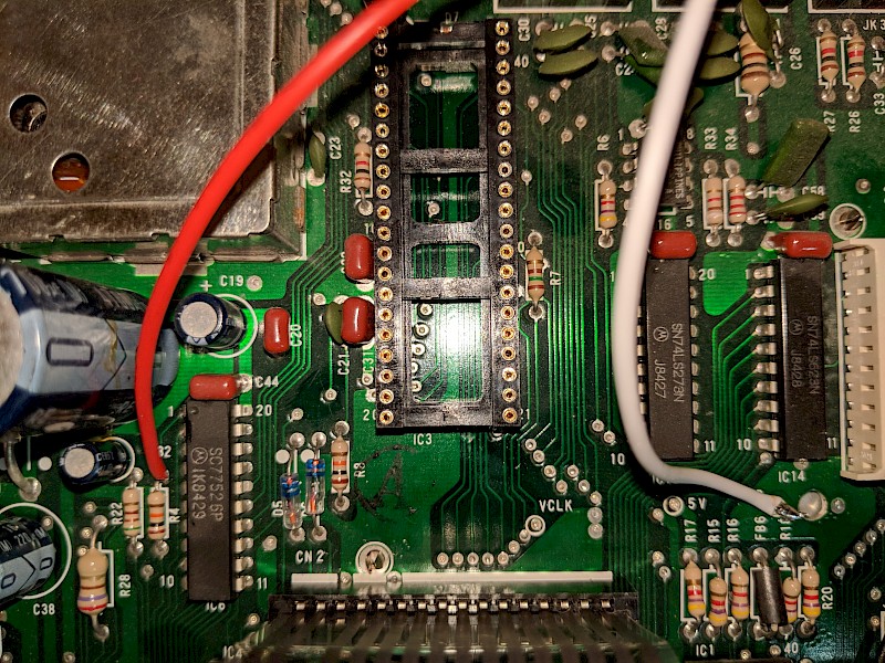
Find the 6847T1 (marked XC80652P) which should be located near the RF modulator (a metal box where you normally plug in your TV), or if you have a composite mod already installed, near that board. Note that in some Korean-made systems, the 6847T1 may be soldered in place and in others it will be socketed.
Also note that in some types of mainboards (not pictured), there may be a 64k RAM upgrade board installed in the white sockets to the right of the 6847. If there is, the system may require modification to convert it to 64k RAM on the mainboard in order to make room. It may also be possible to elevate the CoCoVGA board using a few extra sockets to clear the 64k RAM upgrade board.
If the 6847T1 is installed in a socket, use a small screwdriver to gently pry between the socket and the chip a small amount on one side, and then the other, alternating back and forth until the 6847T1 can be removed from the socket. Alternatively, use a DIP chip puller. Set this chip aside since it will be necessary to reuse it with CoCoVGA.
If the 6847T1 is soldered in place, it will be necessary to desolder it and replace it with a socket. Because CoCoVGA requires a 6847T1 to operate, unless you have a spare, you must non-destructively desolder the 6847T1 and reuse it in the appropriate socket on the CoCoVGA main board. Once desoldered, insert a new socket into the pins where the 6847T1 was once installed and solder each of the 40 pins in place.
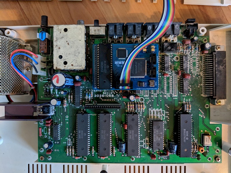
Step 3 - Insert the CoCoVGA main board
Insert the 6847T1 chip removed in the previous step into the CoCoVGA board with the orientation shown. Plug the CoCoVGA main board into the socket where you removed the 6847T1.
Step 4 - Install the CoCoVGA button board
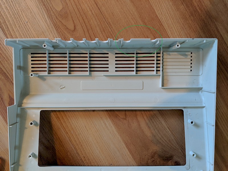
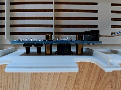
Find a suitable location on the back panel of your CoCo 2 in which to install your button board. Note that due to the number of reinforcing ribs inside the case, the only reasonable place where a button board may be installed is over the RF modulator and power button, as pictured.
PREPARING TO USE A PCB TEMPLATE TO INSTALL THE BUTTON BOARD
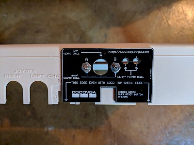
If an installation template was included in your kit, then tape it to the back of your CoCo 2 but ignoring any recommendation about alignment over the reset button.
Start by drilling the two bolt holes (one on either side of the large hole) and then use the machine screws and nuts provided with the button board to mount it in place when drilling the remaining holes. (These steps are described in more detail, below. See "Drilling and installing".)
PEPARING TO USE A PAPER TEMPLATE TO INSTALL THE BUTTON BOARD
If you will be using a paper template, print it at 100%. Do not use "fit to page". Match your ruler against the printed rulers to make sure it is printed correctly. Otherwise, it may be necessary to ask your software to scale it up or down.
Cut out the template leaving some paper available to attach to the back of the top half of the CoCo 2's case.
Paying attention to obstacles inside the case (such as locations for screws and reinforcing ribs), place the template in an appropriate location and attach it using tape. Over the RF output and power switch is likely the best spot.
DRILLING AND INSTALLING
The recommended diameters of the 5 holes are as follows:
- DIN jack - 13mm (about 1/2 inch)
- 2 machine screw holes (on either side of the DIN jack) - 3.5mm (9/64 inch)
- 2 button holes - 4.4mm (11/64 inch)
The 4 smaller holes can be drilled using the appropriate sized bit.
It is strongly recommended that a smaller bit is used to drill a pilot hole for the larger DIN jack. (There is a high risk of tearing or cracking the case!) Then, progressively larger and larger drill bits may be used to finish drilling the hole to the appropriate size. Note that given how soft the CoCo 2 case is, it is possible to run larger bits in reverse to make the hole and then a knife or blade can be used to cut the extruded collar away from the inside of the case.
If a 13mm or 1/2 inch drill bit is not available or won't fit in your drill's chuck, then once the hole for the DIN jack is large enough, a round file may be used.
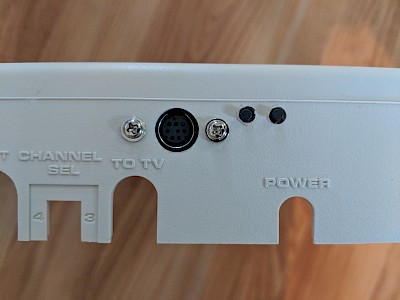
Using a screwdriver and pliers, attach the button board to the case using the included machine screws, standoffs, and nuts.
Step 5 - Install the audio output jack
If appropriate for your installation (that is, your system does not already have an audio output by way of a composite interface), now is a good time to select a place on the back of the system to install the headphone jack. Ed Snider created a video of this installation procedure here. (Note that in this video, the leads on his audio jack are black and white, which differ from those which we are including with the kits. See below for more information.)
Strip a short section of insulation from the ends of the red and white wires. Solder the red wire to either pin 1 of the SC77526P or the lead of the resistor on the same trace. Solder the white wire to ground. See the diagram below for 2 examples of these connections.
Find a convenient location to plug in headphones, amplified computer speakers, or other 1V peak-to-peak audio input device and make sure that the jack won't collide with the power supply, other existing jacks, or the cartridge port area. Drill this hole using a 6mm (about 1/4 inch) drill bit.
Mount the audio jack in the hole that was drilled in the back of the case using the included ring nut.
Step 6 - Connect the CoCoVGA button board
Connect the header connector from the ribbon cable to the CoCoVGA main board. The ribbon cable's connector is keyed and will only fit into the CoCoVGA main board header connector one way.
Step 7 - Close the case
Place the upper half of the CoCo 2 case on the lower half, being careful to avoid pinching the ribbon cable between case halves. Be especially wary of the cable being caught between screw posts - it is possible to inadvertently put a screw through the ribbon cable.
Turn over the Color Computer and insert the 6 screws that were removed in step 1.
Once the case halves are screwed back together, turn the CoCo 2 back over on its base.
Step 8 - Connect the DIN cable
Reattach peripherals and connect the DIN cable between the button board and a VGA monitor.