Overview
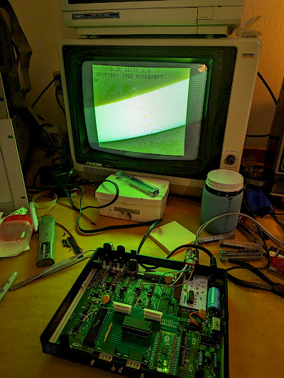
In the 1980s, it was common to take advantage of the 6847s inverse video pin (INV) on the TRS-80 Color Computer to enable light green text on top of a dark green background instead of the opposite. In fact, Tony DiStefano published a Turn-of-the-Screw article called "Green On Black Video: 'Eye Friendly' Conversion" on page 3 or 9, depending on how you count, that covered this.
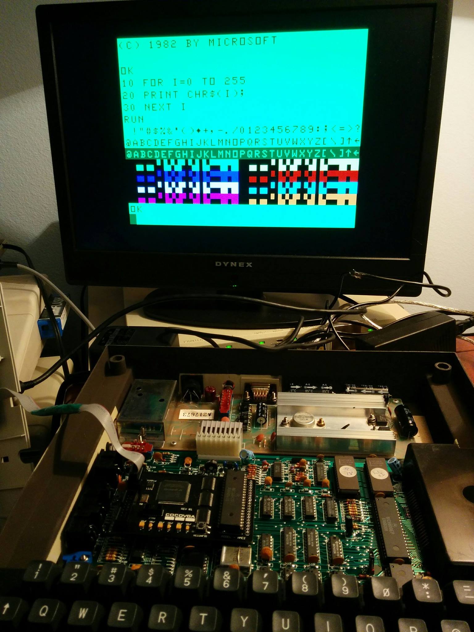
This same feature can be added to the MC-10, since it also uses the 6847 using a single chip piggybacked on top of another along with a switch and some wires. It is also possible to this independently of any other upgrade, such as CoCoVGA or a composite mod - in other words, it works with or without modifications of these types. Even when enabled, this simple hack only affects text, not semigraphics or graphics modes.
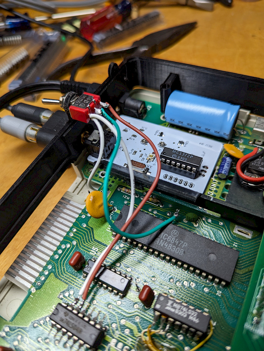
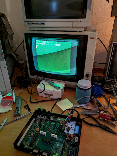
See below for information about how to do this yourself. Photos are included from an installation performed for a user who also asked for a composite mod and a PiKey-10 to be installed. Your MC-10 board may have an RF modulator can in place of the white board in these photos. Additionally, do not expect the mounting hole to be present in a black 3D-printed riser if your MC-10 is stock.
Required Parts
- Small single-pole double-throw (SPDT) switch for enabling and disabling this feature.
- 74LS04 inverter IC. (This may be referred to later as a 7404 or an '04.) If you know how, this could likely be replaced by a single inverter consisting of a small transistor and a few resistors.
- Some light gauge wire, perhaps 24 AWG or smaller.
Necessary Tools
- Phillips screwdriver
- Solderpen/soldering iron
- Solder sucker or other desoldering tool
- Jeweler's screwdriver (straight blade) or dental pick
- Needlenose pliers
- Drill and drill bit, if you wish to mount your switch to your case somewhere
Installation Steps
- Disassemble your MC-10 as described in the PiKey-10 Installation Procedure up to and including step 8. There is no need to proceed beyond step 8 and uninstall the large metal shield that resides between your mainboard and keyboard for this mod.
- Prepare the 6847:
- Identify the MC6847P 40-pin video chip near the RF modulator can near the back of the board. Find pin 32, which is the INV pin. It will be the 9th pin down from the right side of the 6847 chip (the side closest to the heat sink/RF can).
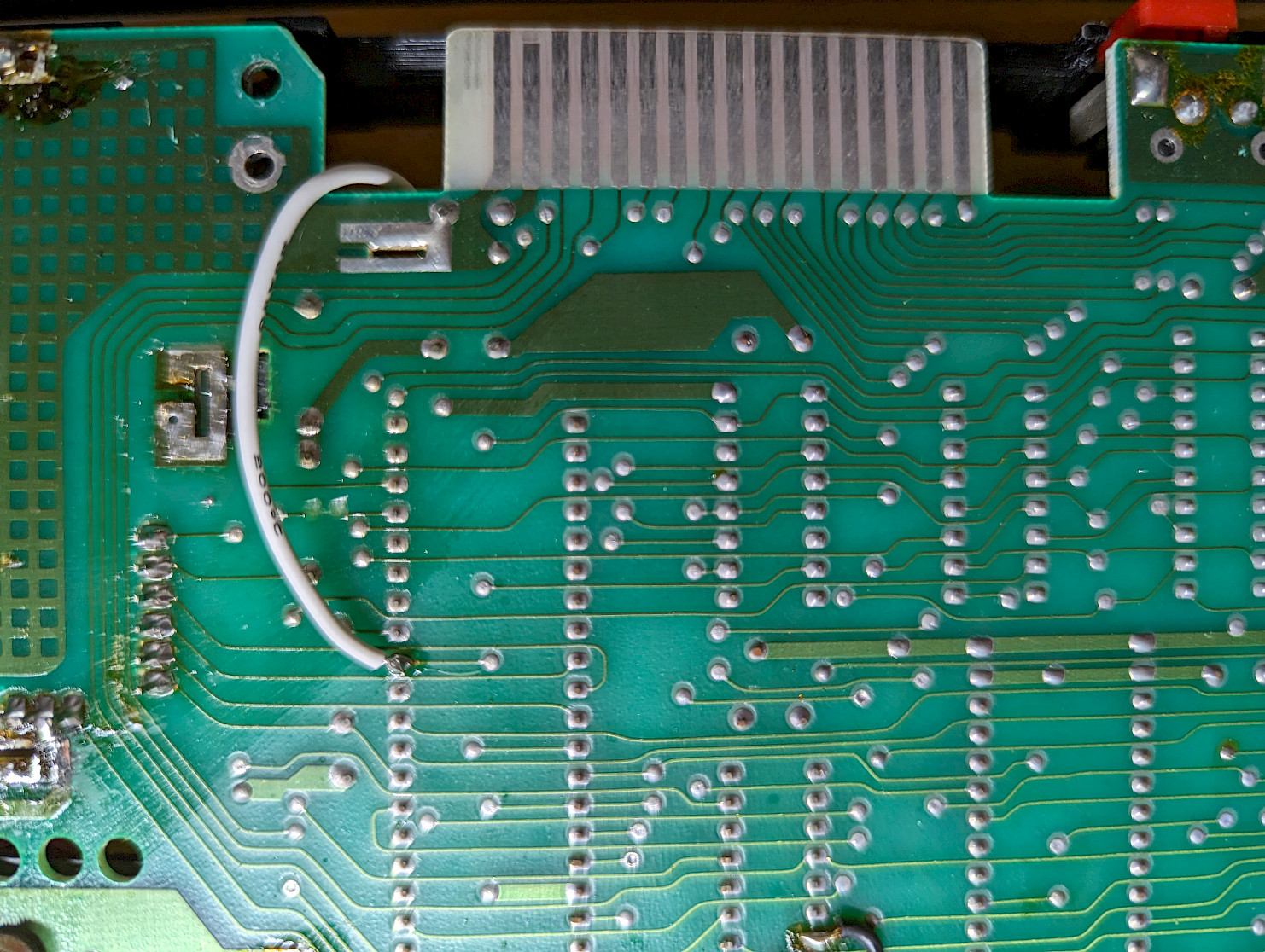
- Turn over the board and identify this same pin. Desolder this INV pin from the underside of the mainboard.
- Turn the board right-side up again and pry out the pin using a dental pick or jeweler's screwdriver. Use the needlenose pliers to straighten this pin out so it sticks out away from the 6847 because you will need to solder to it.
- Piggyback the 7404 inverter:
- Use the needlenose pliers to bend all of the pins of your 7404 hex inverter chip so that they stick out to either side of the chip EXCEPT for pins 7 and 14.
- Place the 7404 IC on top of U6, which is a 74LS367. Be sure that the 7404 has the same orientation as the '367 underneath. Solder pins 7 and 14 of the 7404 to pins 8 and 16 of the '367. It may be necessary to bend pins 7 and 14 just a bit given that it is a 14 pin IC that we're trying to attach to the top of a 16 pin IC.
- Wire up the switch - think about where you might want to mount the switch to your case and make sure you use enough wire in the next steps for the switch to comfortably reach this location:
- Solder one wire between the center tap of your switch and pin 32 (the INV) pin of the 6847 that was pried up earlier. This wire is green in the photos below.
- Solder another wire from one side of the switch to pin 12 of the 7404. This wire is brown in the photos below.
- Finally, solder two wires from the last unused pin of the switch to two locations. These wires are white in the photos below.
- the underside of your mainboard to where you desoldered pin 32 of the 6847
- pin 13 of the 7404
- Test your mod, if desired, and then reverse the order of disassembly - that is, put the mylar shield back on the underside of the mainboard, attach the mainboard to the case, connect the keyboard, and close and screw back together the case.