Overview
The TRS-80 MC-10, as built by Tandy/Radio Shack, was originally limited to 4kB of internal RAM. Although it could later be expanded to 20kB using the official TRS-80 MC-10 16kB RAM pak or beyond with various MCX devices designed by Darren Atkinson, the way the system is designed disallows access to this expanded memory by the 6847 VDG. This means that video memory wraps and redisplays the top 1/3 of the screen at the bottom in either of the 6kB RG6 (256x192 by 2 color) or CG6 (128x192 by 4 color) graphics modes.
In September of 1983 on pages 78-92 of Color Computer magazine, an article describing an MC-10-internal 4-chip piggyback memory expansion modification authored by Dennis Bathory-Kitsz called "Custom Color" was published. This mod added two 2kB memory chips and altered the chip selects and therefore the memory map to give the 6803 MCU (and BASIC) and the 6847 VDG access to a total of 8kB of internal RAM, circumventing the original MC-10 design limitations. Thereafter, the TRS-80 MC-10 16kB memory pak was introduced, and some users discovered memory select decoding limitations causing noise on the display. (See Canadian Retro Things' 2 part series on YouTube.) As documented by Darren Atkinson on his blog and by Geronimus Vanden in this .zip package, there is a one wire fix that should be applied to Dennis Bathory-Kitsz's original mod. Additionally, Ed Snider (Zippster) discovered this issue and not only describes this fix but also reduces the additional piggybacked chip count from 4 to 2 using an 8kB SRAM.
When performing this upgrade on one of this web page author's MC-10s, additional mistakes were detected in the article. In paragraph six on page 86 of the article, it is stated that two chips should be piggybacked atop U5, however, later in the article, it is clear that the second piggybacked chip, the 74LS125, should actually be piggybacked on U6.
For full theory of operation and schematics, please see the original article as well as the information compiled by Darren Atkinson and Geronimus Vanden.
Installation Steps
Note that the author has not tested this modification with the original Tandy MC-10 16kB RAM pak, only with the MCX32-SD, with which it performs flawlessly.
To summarize, here are the steps that should be employed when installing this mod. (Please see the original article or the PiKey-10 USB keyboard adapter installation guide through step 9 for guidance on MC-10 disassembly.) Although it is a perfectly valid and potentially more elegant solution, note that Ed Snider's (Zippster's) approach mentioned above is not followed in this guide.
- Acquire the following ICs:
- Quantity 1: 74LS139
- Quantity 1: 74LS125
- Quantity 2: D4016, AM9128, or 6116P 2k x 8 static RAM (SRAM); 150ns or faster is sufficient
- If you are installing CoCoVGA kit and/or a PiKey-10 USB keyboard adapter (and wish to keep your original MC-10 keyboard functional), desolder the 6847 and/or the white guillotine keyboard connectors, respectively. Doing so will provide additional clearance to install this internal 8kB RAM piggyback mod.
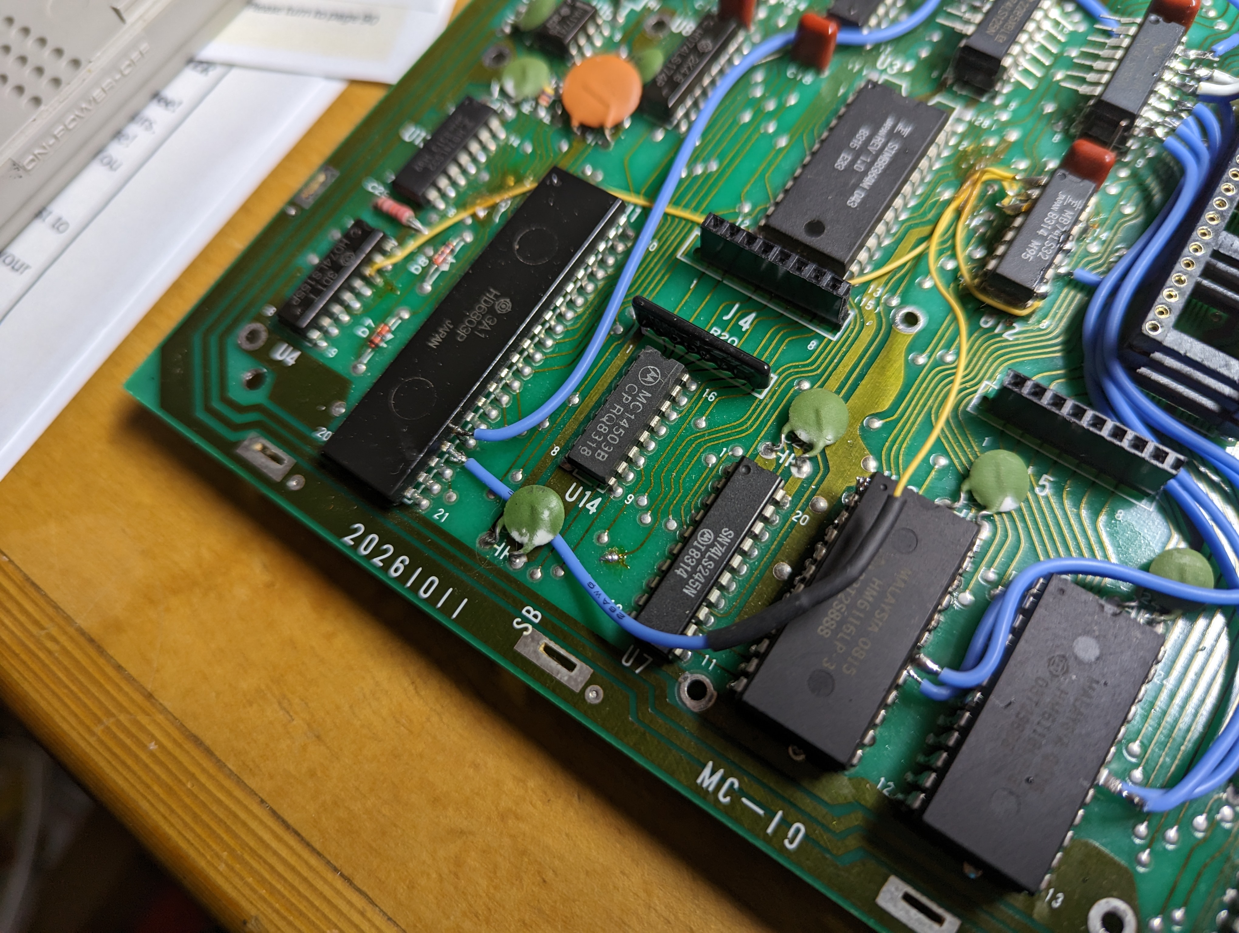
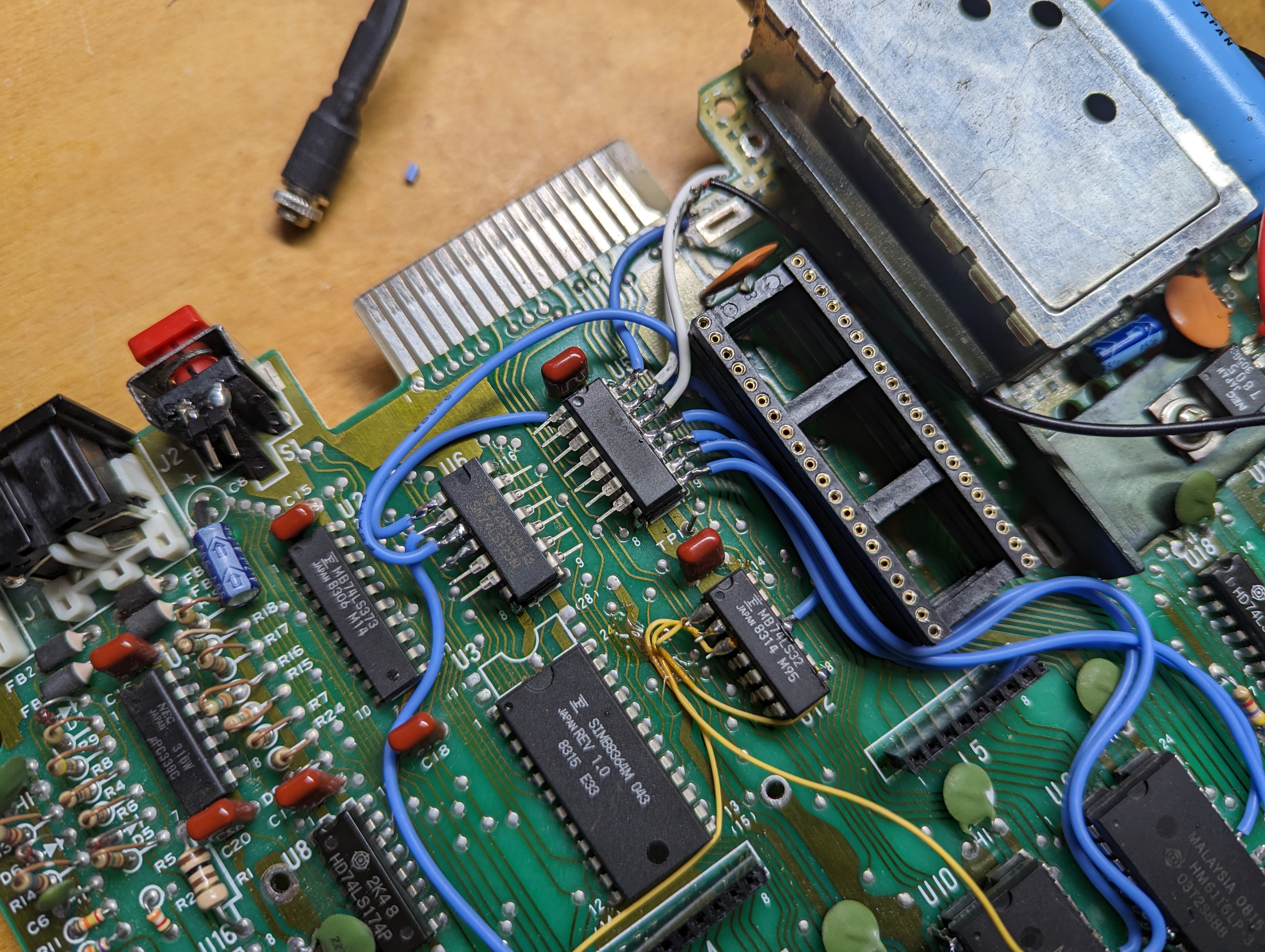
- Paraphrased from Dennis Bathory-Kitsz's article: "Bend all the pins of the 74LS139 up and parallel with its body except 8 and 16. Mount the 74LS139 on U5 with the notch pointing in the same direction, and solder power pins 8 and 16 to U5['s pins 8 and 16, respectively]."
- Corrected from the article: "Bend all the pins of the 74LS125 up and parallel with its body except pins 7 and 14, bend these slightly so this 14-pin integrated circuit fits on [U6], which is a 16-pin device. Mount it in the same direction as [U6], and solder pin 7 to [U6] pin 8, and pin 14 to [U6] pin 16."
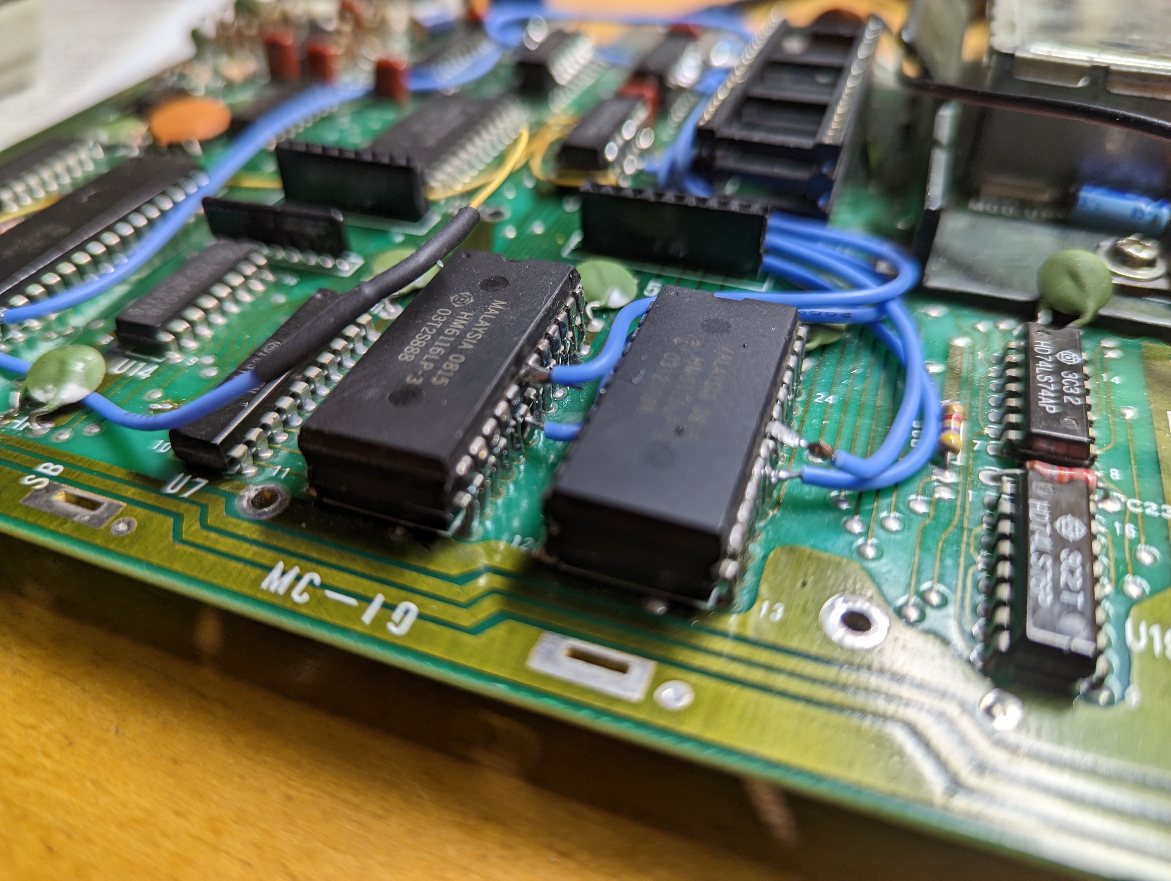
- "Now mount the two memories. Bend up only pin 18, and solder pins 1-17 and 19-24 to U10 and U9, respectively. Be very careful when soldering to the memories below - do not get them too hot, do not create solder bridges, and make sure all pins are soldered. Use a magnifying glass to verify all connections are clean and tight."
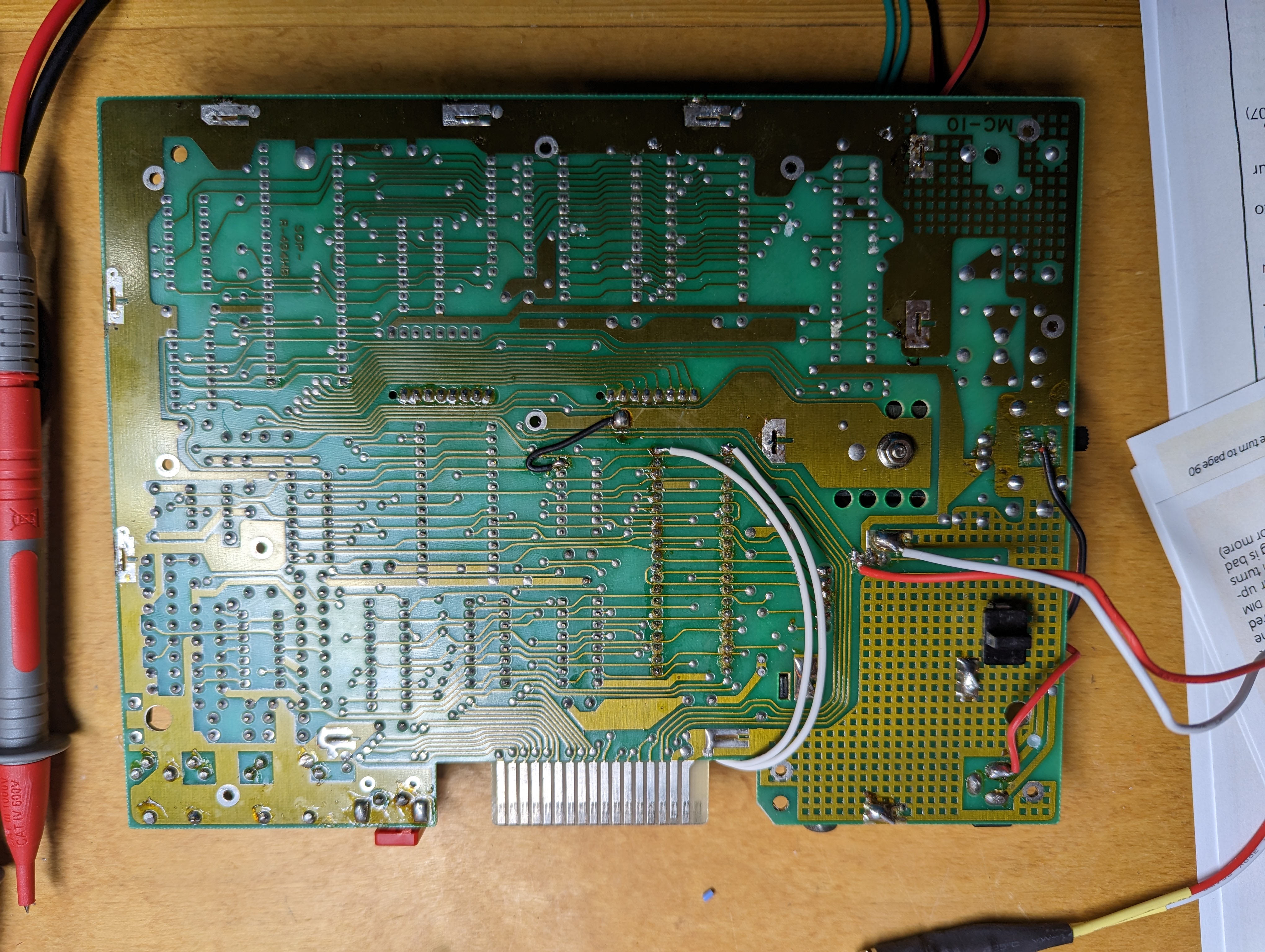
- "Now turn the board over. Locate the traces leading from pin 18 of each memory chip. Cut each trace through with a sharp tool; this removes the select lines from the memories. Return the board to the top side." (The author of this web page has used a dremel with a small grinding wheel to cut these traces, or with help, heated the pin from the underside of the board while someone else pried these pins out of the board. A dental pick or drill and drill bit could also be used to cut this trace.)
- "There are three wires leading from Radio Shack's corrective piggyback. Remove the wire leading to a plated through-hole [via] at the lower edge of the board. Verify this is the hole leading to the CPU (U1) pin 25. Move it to the CPU pin 24." It will likely be necessary to extend this wire using an additionally-supplied wire segment; remember to insulate the junction between the two wires with electrical tape or shrink tubing.
- "Now route the following wires (this order is probably the easiest): P means piggybacked IC:"
- "U5 pin 1 to U6P pin 1."
- "U6P pin 2 to U1 pin 25."
- "U5P [pin 15] to [U5P pin 8 or other GND]." This is the correction detailed by Darren Atkinson or Geronimus Vanden which resolves display noise.
- "U5P pin 14 to U12 pin 11." Note that U12 is the bottom chip of the factory-installed piggyback fix.
- "U6P pin 3 to U5P pin 13."
- "U11 pin 20 to U12 pin 11." It may be more convenient to attach U11 pin 20 to U5P pin 14. Note that if a socket is to be installed in place of the 6847 for the purposes of a video upgrade, it may be appropriate to use a longer wire to reach this pin on the underside of the MC-10 mainboard PCB or to do this connection completely on the underside of the board.
- "U11 pin 21 to U5P pin 13." Note that if a socket is to be installed in place of the 6847 for the purposes of a video upgrade, it may be appropriate to use a longer wire to reach this pin on the underside of the MC-10 mainboard PCB.
- "U5P pin 12 to U9 pin 18."
- "U5P pin 11 to U10 pin 18."
- "U5P pin 10 to U9P pin 18."
- "U5P pin 9 to U10P pin 18."
- Resume installation of a 6847 socket for your 6847 or CoCoVGA or installation of the standard header connectors for the PiKey-10 USB keyboard adapter if either of these were already intended and underway.
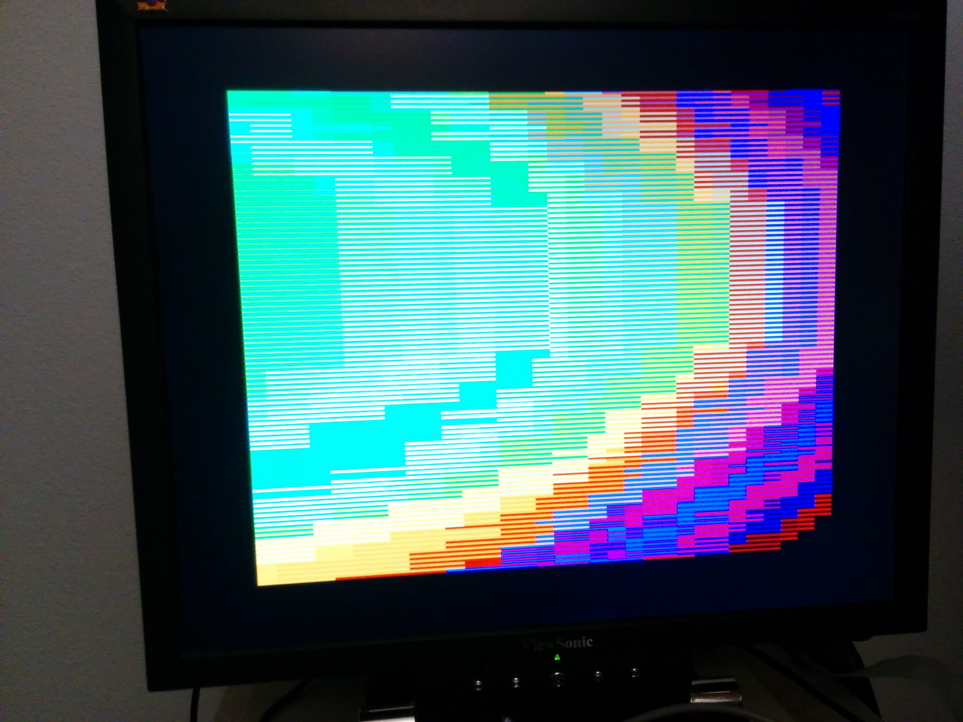
Verifying Correct Installation
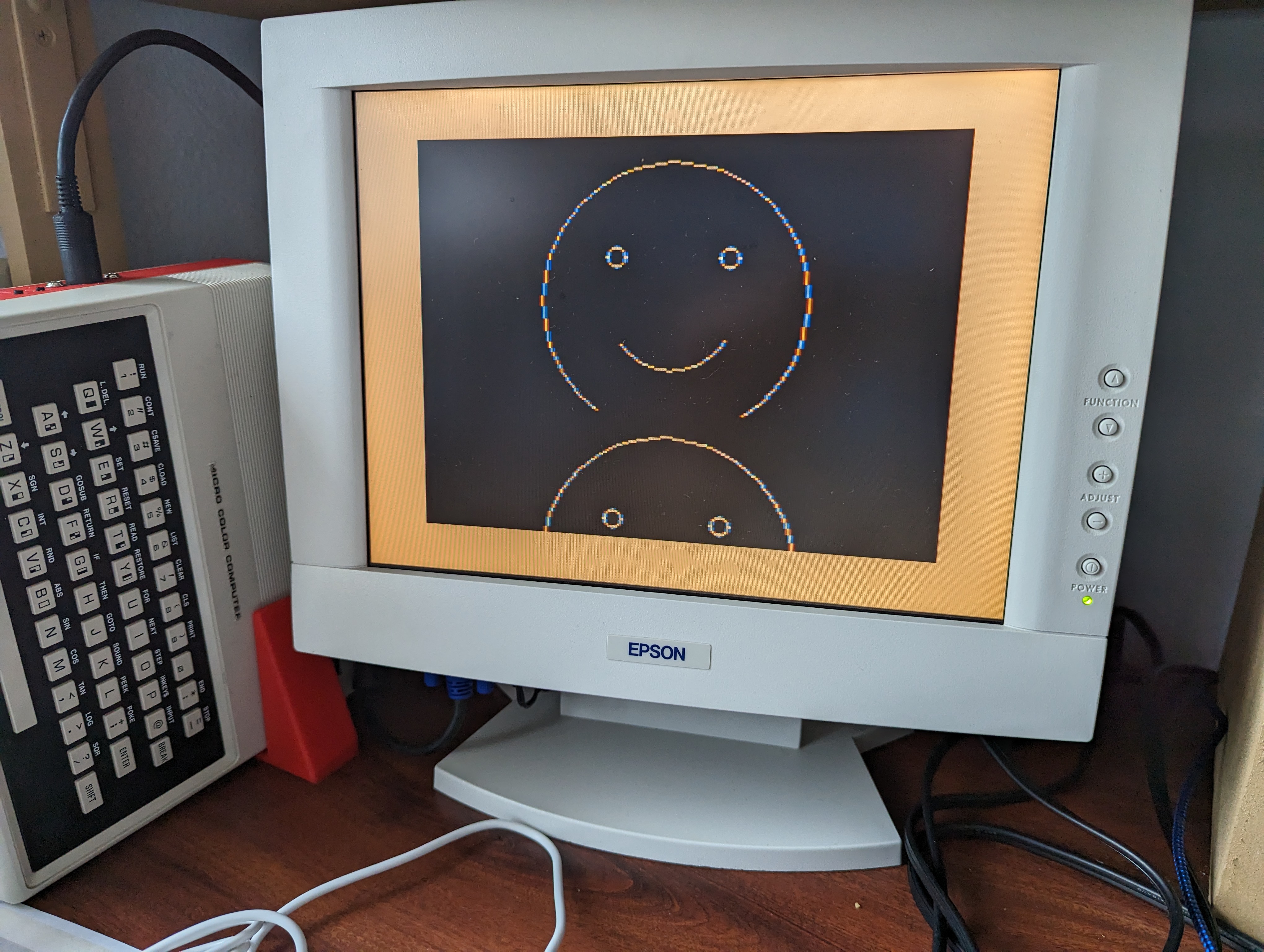
PMODE 4 MCX BASIC Example (bouncing smiley face)
10 PMODE 4,1

20 SCREEN 1,1

30 FOR I=64 TO 127 STEP 4

40 GOSUB 100

50 NEXT I

60 FOR I=127 TO 64 STEP -4

70 GOSUB 100

80 NEXT I

90 GOTO 30

100 REM DRAW FACE

110 PCLS 0

120 CIRCLE (127,I),64,1

130 CIRCLE (100,I-21),5,1

140 CIRCLE (154,I-21),5,1

150 CIRCLE (127,I),32,1,1,.1,.4

160 WAIT 300

170 RETURN
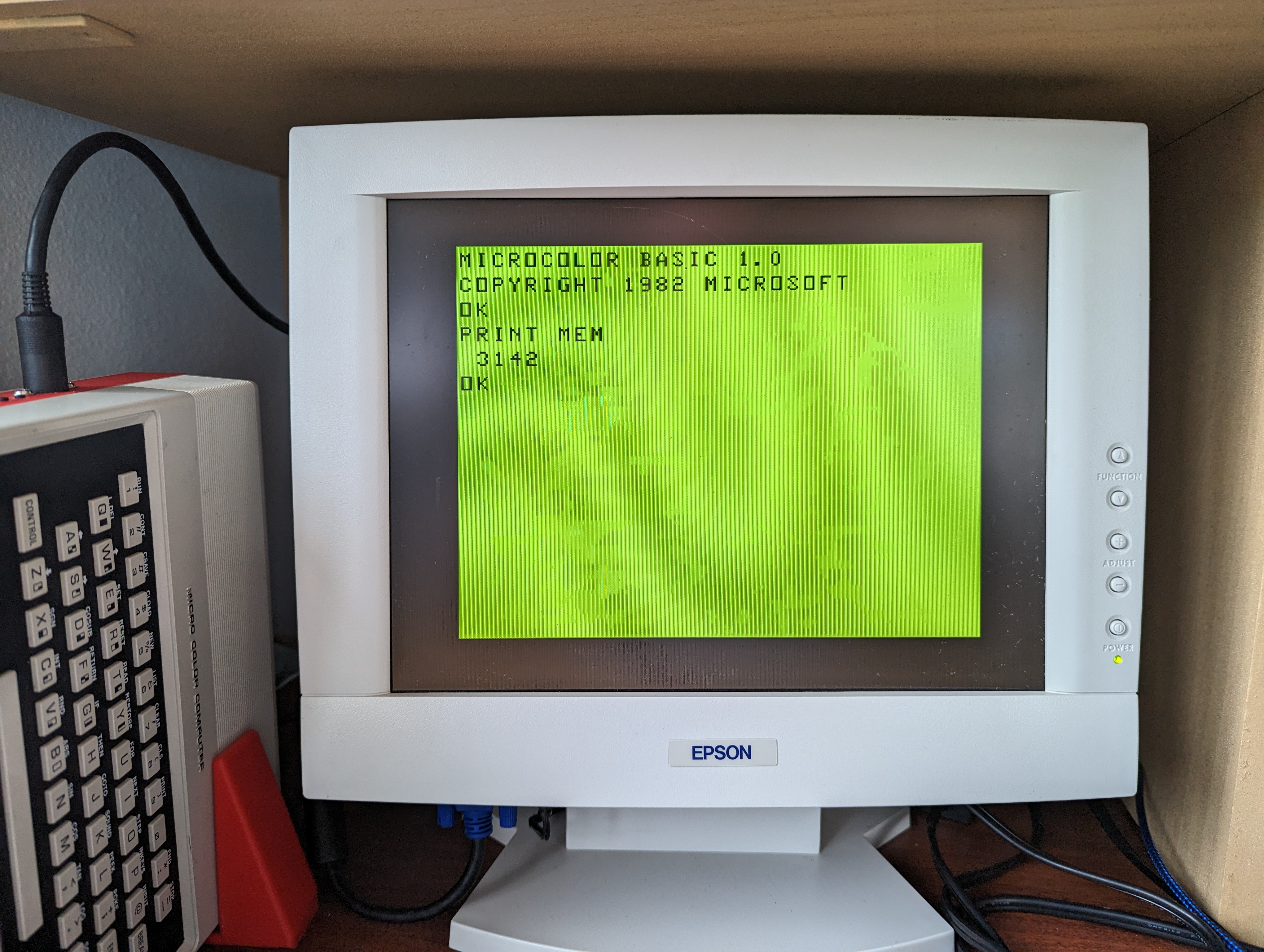
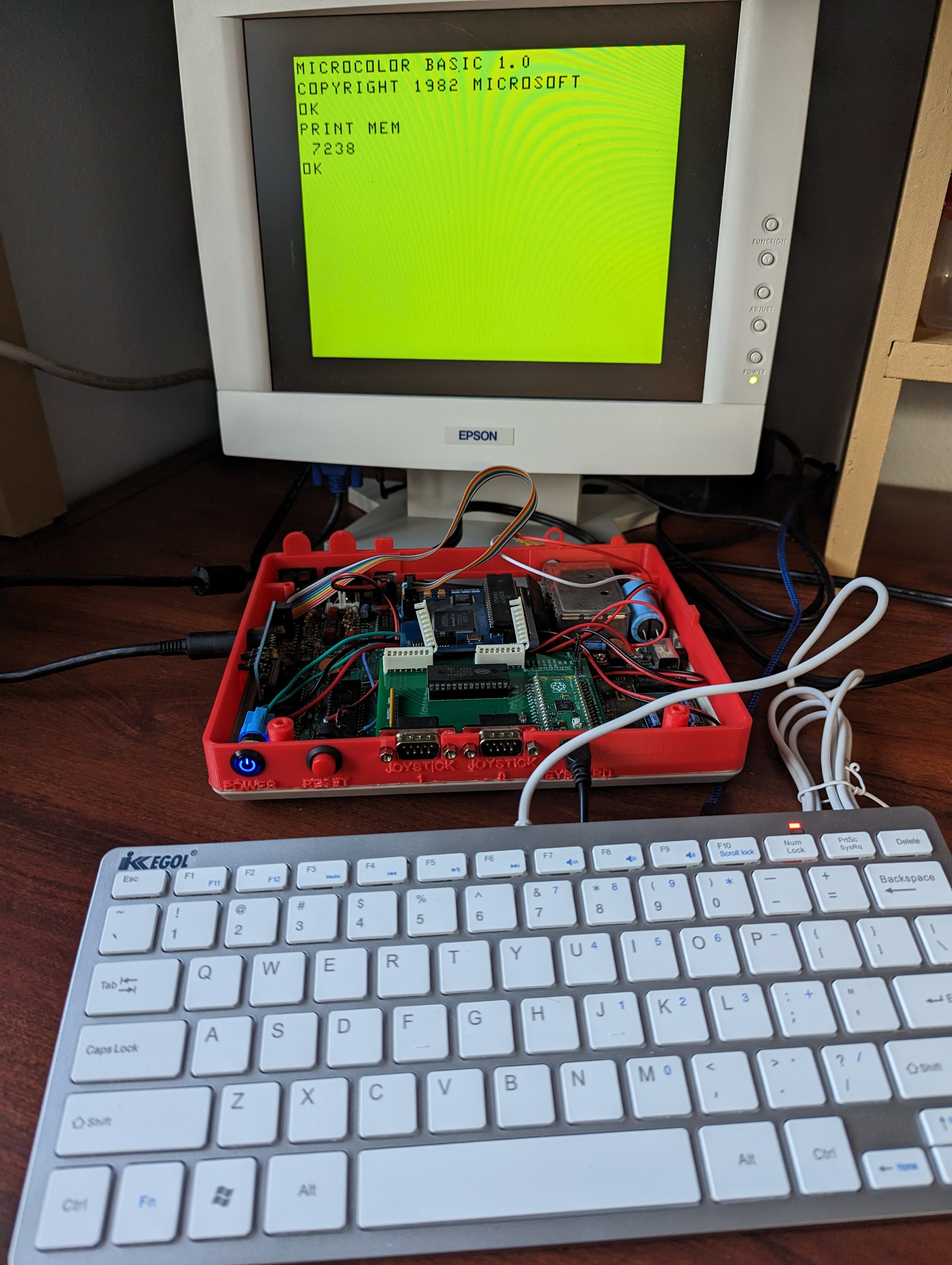
Before
Note that PRINT MEM reports 3142.
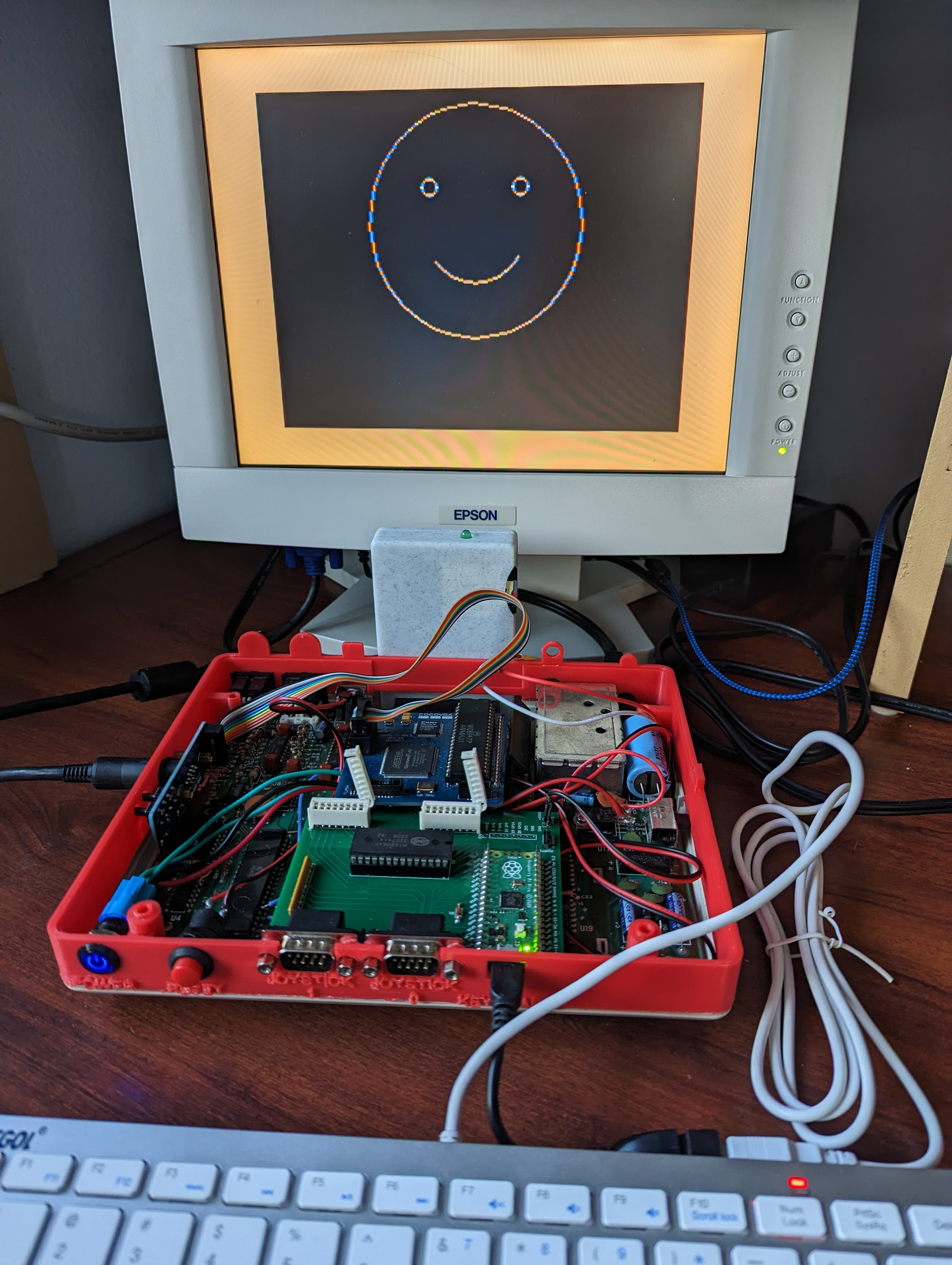
After
Note that PRINT MEM reports 7238.
For additional troubleshooting and debug suggestions for this mod, please see the original magazine article.
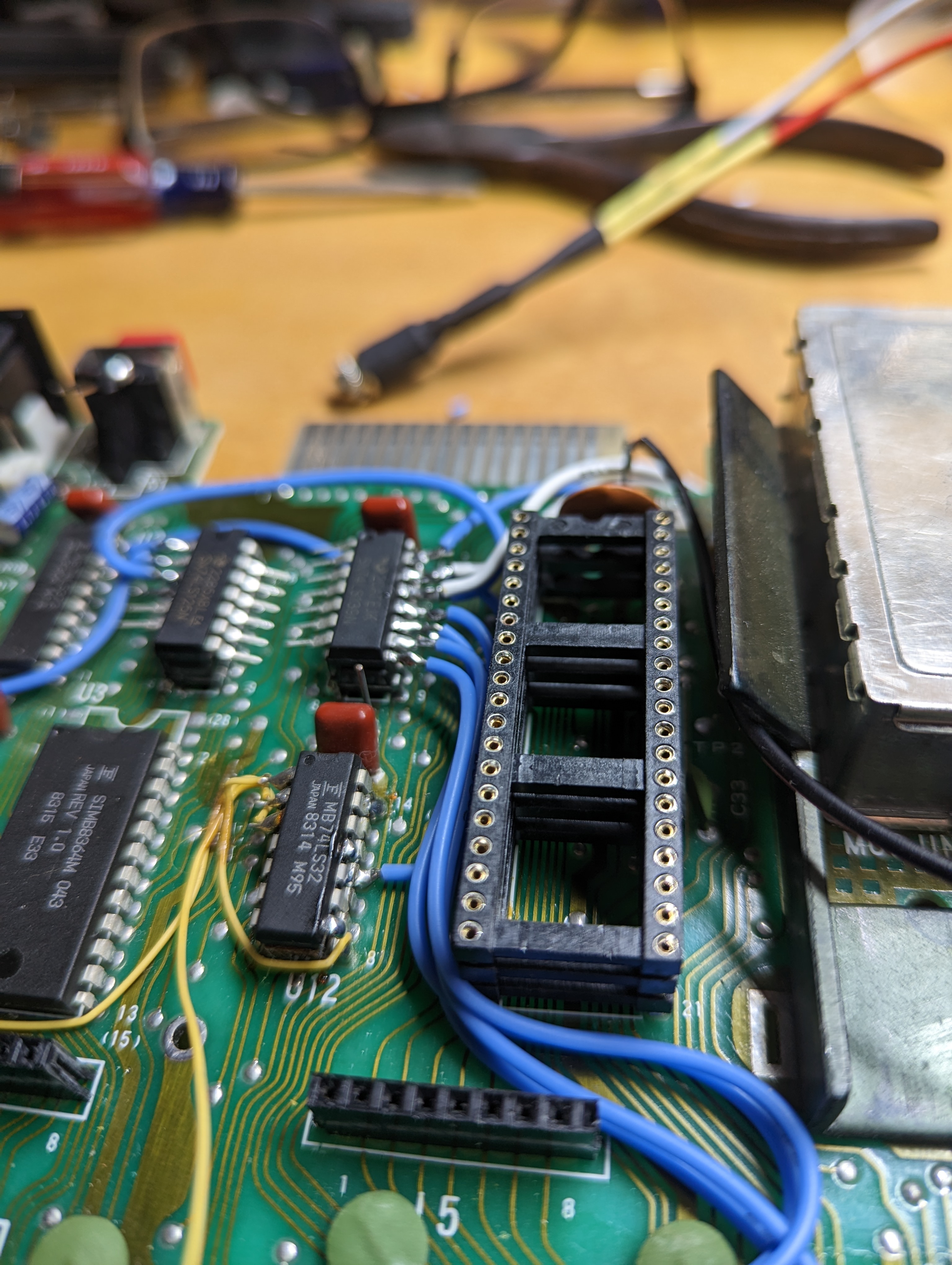
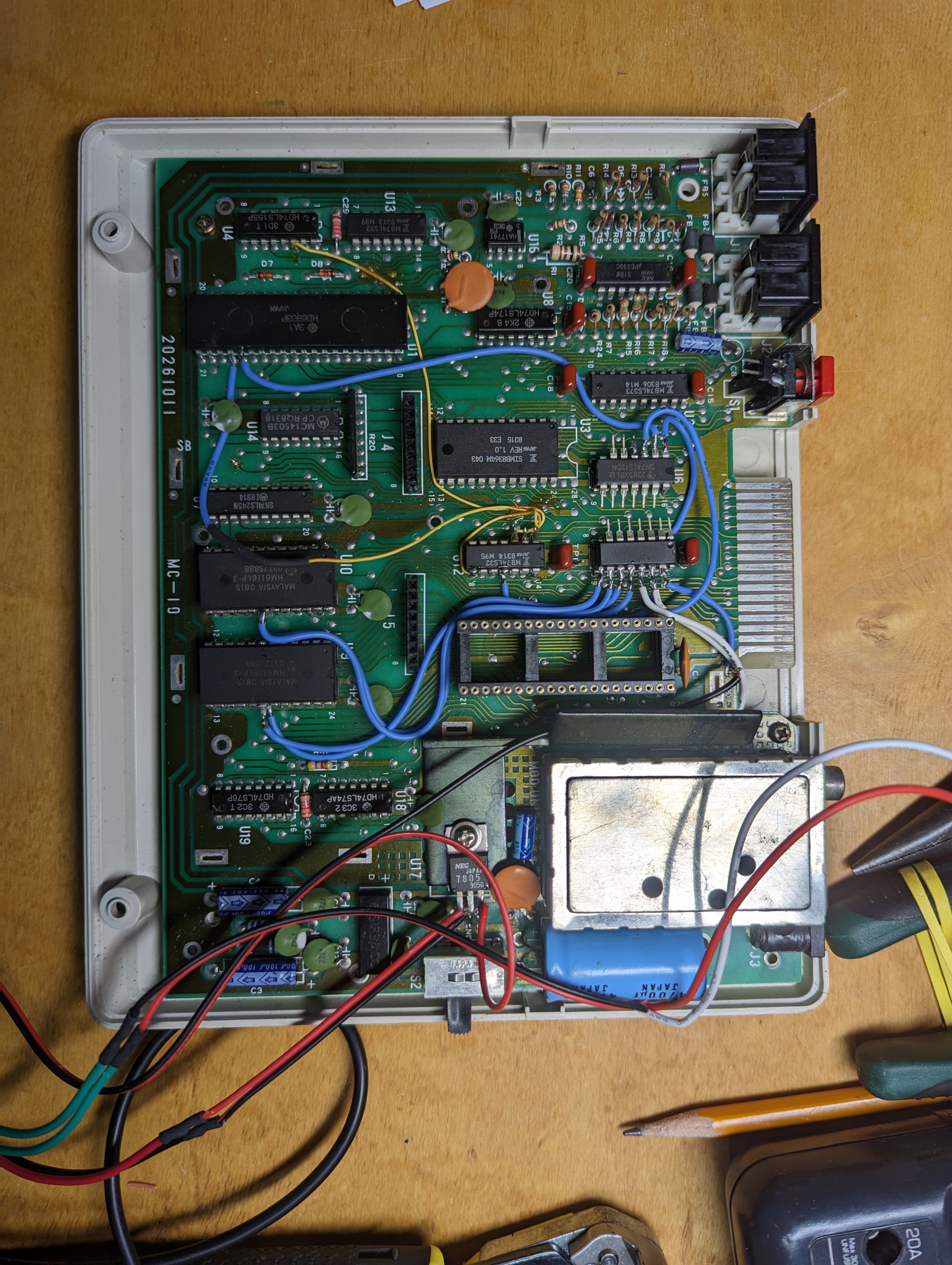
Installation Photos